Fires, record temperatures, and megastorms: "Highway To Hell" (Fossil Fuel Version).
Search This Blog
Monday, July 8, 2024
Sunday, July 18, 2021
Replacement filters for Sears 2 gallon Clean Carry vacuum model 113.177135, Filter # 9-16949
Sears no longer makes the replacement filter for the 113.177135 two gallon vacuum cleaner. The original part number of the filter was 9-16949 or 16949.
Luckily there is an aftermarket replacement filter that fits almost perfectly. The filter is the Vacmaster VRC5. Although it says it is made for 5 to 16 gallon shop vacs, it fit well on my Sears 113.177135 two gallon Clean Carry vacuum. I bought a three pack of the cloth filters on eBay for about $12.00. The dimensions of the VRC5 filters are 10 inches wide at the bottom with the filter flattened out, and about 9.5 inches long. It has a sewn-in elastic collar at the top that holds the filter in place on the cage inside the vacuum.
The dimensions of the cylindrical plastic cage inside the vacuum are 5.5 inches in diameter by about 5 inches long. Although the Vacmaster VRC5 filter is longer than five inches, it is tapered, so it fits almost perfectly.
I had a hard time finding information on replacement filters on the web, so I hope this information is useful for you.
Saturday, May 22, 2021
Over the last few months I've been remembering my visit to Brazil as part of a Rotary Club Group Study Exchange to the state of Rio de Janeiro 30 years ago in March and April of 1991. Thanks for joining my journey as I converted my slides to digital images.
We had to write a report of our visit when we returned to the US, and here was the last paragraph of my 1991 report:
"The Brazil GSE experience was truly a once in a lifetime opportunity. It was busy, but I learned so much about Brazil, and made some good friends. I will always remember the hospitality I experienced with the families I stayed with, and I hope to see them again. I would like to return to Brazil with my family and I hope to continue studying Portuguese. Thank you for this unique and wonderful experience."
I did return to Brazil in 1998 with my family, and I have maintained contact with some of our hosts over the years, including our incredible Brazilian Rotary Club exchange trip organizer Gilson Menezes . During the pandemic, I studied and practiced Portuguese consistently, and have finally reached a comfortable conversational level in Portuguese. It only took 30 years. Brazil here we come again!
Here's a video compilation of the pictures I digitized and shared over the last few months. Thanks to Brazilian jazz pianist and singer Eliane Elias for this great tune called "Aquarela do Brasil" or "A Watercolor of Brazil."
Sunday, April 12, 2020
Saturday, April 11, 2020
Saturday, November 2, 2019
Wednesday, January 18, 2017
Making a Replacement Part for the Unavailable Three-Wire Defrost Thermostat 63001599, KS-2N-MF, AP4072639. Replacing the Unavailable Defrost Heater AP4072093 or 63001595.
1/18/2017: The defrost thermostat went bad on my 10 year old Admiral 21 Cubic Foot refrigerator model LTF2112ARW. I knew that because there was no continuity between the white and orange wires when the thermostat was submerged in a cup of ice water. There was also heavy icing and frost on the back wall of the overhead freezer compartment, and the refrigerator below was not cooling. When I looked for the necessary replacement part on the web, 63001599, every place I went said that the part was no longer available.
Hoping to keep the fridge alive, I saw that the broken thermostat was labeled KS-2N-MF, with a rating of 16.2/-5.4. When I Googled the part number, I found it was made by a Korean company, and all the specifications for the part, including a schematic were found here: http://www.pnacorp.com/mobile/sub02_08_01.html
Looking at the specifications and schematic, the original three wire thermostat included a small thermal fuse (73C-84C) as well as a 60 degree F/16.2 degree C thermostat inside the sealed black casing. The original part has three wires: a white wire, an orange wire and a brown wire. The brown wire actually allows current to flow to the defrost heater when the thermostat is closed, and when the temperature in the evaporator area near the thermostat exceeds 60F, the thermostat opens and shuts down the heater. The thermal fuse is evidently there to protect the system from a heater malfunction, and resides between the white and brown wire based on continuity testing and the schematic.
Before disassembling and reassembling the refrigerator, I unplugged the unit.
To replace the unavailable part, I purchased the components of the thermostat and made my own.
Here are the parts I used:
- Supco ML60 thermostat. This thermostat opens at 60F and closes at 40F. The original thermostat opened at 61.6F/16.2C and closed at 37.7F. (a 22.3F/5.4C degree range). This was available for $2.95 at McCombs Supply.

- Supco SL247 clips for attaching the thermostat to the evaporator tubes. ($2.70 for a pack of 3 at McCombs).

- A Microtemp 73C thermal fuse on Ebay. ($2.50)
To make the part:
1. Take a picture of the original installation
2. Cut off the two-conductor, white plastic connector with orange and white wires, leaving about 3 inches of wire coming out of the connector.
3. Slide a piece of medium size heat shrink tubing over the white wire, from the white connector almost up to the end of the wire cut. Strip away the insulation on the white wire, and crimp it to one side of the new thermal fuse using a small size crimp connector suitable for 16 gauge wire. It doesn't matter which end of the fuse you connect to the wire.
4. Cut off the entire length of the brown wire from the old thermostat.
5. On the new part, crimp the brown wire and one of the new thermostat wires to the free end of the new thermal fuse.
6. Pull the heat shrink tubing over the new connections, and heat the ends of the shrink tubing to seal the connections. Don't heat the ends too long, and don't shrink the tubing over the fuse or you might blow the thermal fuse.
7. Slip a short piece of heat shrink tubing on the free orange wire and crimp connect the orange wire to the remaining wire from the new thermostat. Pull the heat shrink tubing up over the new connection, and shrink it tight over the crimp.
Here are some pictures of the new part before applying the shrink tubing:
| Finished part with connections covered and heat shrink tubing ends sealed. You can add some silicone sealant to the ends if you want. |
To finish, I attached the new thermostat to the evaporator tubing using one of the new clips. Route all the wiring towards the back of the freezer box, behind the existing evaporator tubing. Plug everything into the connectors in the evaporator area. I reassembled the freezer compartment, ice maker, etc. and plugged in the refrigerator.
Here's a picture of the new part inside the freezer/evaporator area:
This fix worked for me in replacing the no-longer-available 63001599 Korean three wire thermostat. The total cost for parts was about $15.00. The refrigerator is now cool, and I hope to get another 10 years out of this appliance.
2/25/17 Update: When I replaced the thermostat as described above, it did not stop ice from building up on the evaporator. I know the old thermostat was bad because I tested it, so the work above was necessary, but it didn't completely fix the refrigerator. The other parts that control the defrost heater circuit are the defrost timer and the defrost heater itself. I checked the defrost timer by manually turning it to the defrost heater cycle (which shuts off the compressor) and found that it was advancing through the cycle properly. While testing the timer, I noticed that the heater which is attached to the evaporator coils was not heating up--I couldn't feel any warmth through the back wall of the freezer. When I took the old heater out, I noticed it had a burned spot on the glass near one end, and there was moisture inside the tube. I definitely needed to replace the defrost heater.
When I went to the appliance parts websites to find a replacement, I faced a familiar and aggravating problem with this refrigerator. The part I needed, AP4072093 or 63001595, was no longer available. The original glass tube heater used in the refrigerator was 24 inches in length. I found a possible replacement glass tube heater that was about 24 inches long in the Supco SH267 part, but I noticed it was rated at 500W. The tag on the inside of my Admiral LTF2112ARW refrigerator said the unit uses 3.8 amps, or 456W at 120V. I really didn't want to get a heater over 450 watts, so I found the Supco SH320 Tube Heater that is rated at 450 watts.
The only problem with this Supco SH320 heater is that it is shorter (20 inches) and has a thinner glass tube diameter than the original. Nevertheless, I bought the heater. When it arrived I cut the plastic electrical connectors off the old heater and soldered them onto the new Supco SH320 heater, using heat shrink tubing to protect the soldered splices. The original defrost heater simply hung from the bottom of one of the lower evaporator tubes by two small steel clips. I was able to remove those clips and move them a bit toward the middle of the evaporator unit so they would support the new, shorter heater. You have to kind of fit the clips into the aluminum fins that fill the spaces between the evaporator tubes and make sure the clips snap onto an evaporator tube. I also crimped the clips a bit so they would grab the thinner diameter tube. I put in the new heater tube, centering it in the width of the evaporator unit, and reconnected the wiring.
The refrigerator has been running for about a month now with no frost buildup on the evaporator tubes. The Supco SH320 450W heater is adequately keeping the evaporator free of frost, with the thermostat shutting it off when the temperature rises above 60F in the evaporator area. Fixing the frost problem required both a new thermostat and a new defrost heater, and has kept this 10 year old refrigerator alive. The total cost for the parts needed to construct a new 3 wire thermostat and using the new Supco SH320 quartz tube heater came to about $35, including shipping costs.
Thursday, February 21, 2013
Forward on Climate Rally; Washington, DC; 2/17/13
On Sunday, February 17, 2013 around 40,000 people met at the Washington Monument in Washington, DC to urge our government to take action on the burning of fossil fuels that contributes to climate change, and to ask the president to stop the Keystone XL pipeline that would bring Canadian tar sands oil to the Texas gulf coast. The climate change rally and march was primarily sponsored by 350.org, the Sierra Club and the Hip-Hop Caucus, but participants came from many organizations, including several faith-based groups such as the Sojourners. I went to Washington on one of 11 buses that carried over 500 people from our area to the rally.
On the way back from DC in the bus, we each shared one word that characterized the day. Words like encouraging, energizing, active, informative, generational, diverse, communicative, transformational, historic, loud, creative, and fun floated up from the tired marchers. When I got back and I saw the pictures that I took in this album, one more word to characterize the day was quite evident to me—happy. In almost all of the pictures I took, people were smiling. They were smiling about a large group finally coming together to make our voices heard on climate change. They were smiling about the chants we sang such as “Hey Obama, we don’t want no climate drama” as we marched around the White house. They were smiling that old and young alike were of one mind that there is no “Planet B.” They were smiling at the creative ways that people expressed their concerns about our energy and environmental futures. They were smiling about the shared purpose and the knowledge that something important happened on this cold and blustery day in February when people raised their voices. It was a good day.
Wednesday, November 14, 2012
The Colors of Spain
Here are a few pictures from our trip to Spain in October 2012. The pictures were taken at various locations in Madrid, Sevilla, Écija, and Córdoba.
Friday, March 9, 2012
Grid Tie Solar Plug and Play in the US
While other countries have commercially available grid tie solar plug and play systems (http://solar-power-station.co.uk/), the US does not. At least one US company has committed to such a product (http://clarianpower.com/), but it is not yet available.
As part of the US DOE’s SunShot initiative to support a multi-source approach to meeting the country’s energy needs, a meeting was held in Washington, DC on October 27, 2011 to focus on the development of plug-and-play solar technologies in the residential sector. The purpose of the workshop was to identify the current barriers and possible solutions for these technologies. Over 60 people attended the conference, including representatives from utilities, code officials, inverter companies, PV module companies, and installers.
Here is a summary of the results of that meeting: http://www1.eere.energy.gov/solar/pdfs/solar_plug_play_2011.pdf
Although there seemed to be a lot of off-topic discussions, a few big issues emerged:
1. How to deal with current permitting requirements for electrical issues.
Suggestions for dealing with electrical safety issues to avoid permitting and inspections by local code enforcers seemed to be fairly straightforward:
--UL listing for PV system: NEC 90.7 Equipment that is listed “need not be inspected at the time of installation.”
– Develop a standard PV plug at the utility meter (or elsewhere)
– Changes to the National Electrical Code are required (we are on writing code council)
– Smart, PV-ready circuit breakers.
2. How to deal with current permitting requirements for structural safety issues.
Suggestions for dealing with structural issues such as modules resisting windy conditions and PV systems compromising building structures were less imminent and not as practical.
--Can we build a PV system on a residential home that is
• Light-weight (polymer)
• Requires no roofing penetrations (can’t have roof leaks)
• Requires few (or no) tools to install
– Can we design a PV module/array that fits around a roof like a fitted sheet on a
bed?
– Establish requirements for solar ready houses (standardized roof jacks)
– Consider composites, polymers… integrating frames and mounting systems can dramatically reduce weight.
3. There was also discussion about how to integrate Plug and Play Solar arrays with smart grid issues.
I learned a few things from reading the summit results. The electrical safety concerns seem to be fairly easily overcome. Many of the obstacles are not difficult safety barriers, but more code-related. Limiting the Watt size of plug and play systems on each branch circuit allays overloading concerns.
According to NEC 90.7, UL listing is not required, but if non-UL listed equipment is used it must be inspected at the time of installation. Some advocated a UL listing for the entire system (modules, wiring, inverters, connectors), while others advocated each component be UL listed.
There are concerns about using the standard three prong plug to simply plug into an existing outlet. They talked about developing a USB like plug specific to PV systems so people aren’t exposed to live conductors on the male end of the plug. I don’t really understand the concerns here. An anti-islanding grid tie inverter shuts off when it is pulled out of the outlet, effectively cutting off current to the plug, and protecting the user from contact with exposed conductors. The British system uses a standard outlet connection with anti-islanding China-made inverters.
Given the seeming lack of consensus on the structural issues associated with attaching plug and play to buildings, it seems simply requiring ground mounting makes the most sense. I think keeping people without fall protection off of roofs is a good thing. Many commercial solar firms working on roofs don’t even provide fall protection systems to their employees, and there are several deaths from roof falls annually in the business.
As a result of the workshop, in January 2012 the DOE announced a 3 year grant program to fund studies on plug and play solar issues that came up in the workshop: https://eere-exchange.energy.gov/Default.aspx?Search=plug&SearchType=. It appears that it will be a few more years before commercial plug and play grid tie systems hit the markets in the US, and with the desire to incorporate smart grid components into the system, more than a simple inverter will be required.
So why is the whole issue of plug and play grid tie solar so important? A 500 watt back yard grid tie system generates about 650 kWh of electricity each year where I live. In my local utility area, that translates to about 9% of the average residential customer’s annual electricity use. Besides saving money for the customers, widespread use of these systems could slow the need for new power plants and drastically reduce carbon emissions. I also recently read the book “The Big Thirst” by Charles Fishman, and learned that steam generating power plants use over 200 billion gallons of water a day to make steam and cool heat exchangers (http://powerscorecard.org/issue_detail.cfm?issue_id=5). Solar modules require no water for cooling.
While we wait for commercially available plug and play grid tie systems, DIYers need a UL-listed DC to 120V AC inverter, or guidelines for inspectors when non-UL listed equipment is installed, and code revisions that allow connection to the grid. If other countries have already overcome plug and play solar obstacles, why can’t we? As the world becomes flatter and hotter, is a three year wait for plug and play solar that is already available elsewhere acceptable?
Monday, February 27, 2012
Our Experience with the Giani Granite Countertop Paint Kit—February 2012
For several months my wife and I discussed how we could give a makeover to our old laminate kitchen countertop. We don’t have a big countertop. The sink countertop is L-shaped, 8 feet in length, with the L part extending about 18 inches from the 2 foot wide main section. We also have a 2 foot by 2 foot desk section that matches the sink countertop. All told, we have 11.5 feet of standard 2 foot wide countertop.
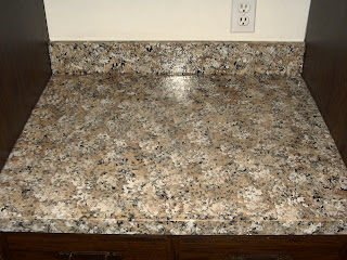
We investigated our makeover options in the typical fashion. After being shocked by the megaprice of granite, and even the $600 cost of replacing the existing countertop with another laminate top, we investigated tiling the countertop. I even bought a tile saw. Before buying the tile, we ran across some information on countertop paint kits, and visited the Giani Granite website http://gianigranite.com/indexcountertoppaint.html to learn more. Encouraged by the testimonials both on the Giani site and elsewhere on the web, we decided to try the kit. It appears that in the last few years Giani’s marketing strategy has been to give away kits to bloggers in return for writing up their experiences. We are not one of those bloggers. We bought the Giani Sicilian Sand kit on Amazon.com for $69.95 including shipping. Here is a “before” picture of our countertop:
| Our countertop was in great shape structurally, but had many superficial scratches and stains. The color also did not go with the laminate floor we put in a couple years ago. |
| There is a matching desk section that we use for the microwave oven. |
After watching the instructional DVD and armed with the detailed Giani paint kit instructions, we started the project on Saturday morning, February 18. We were aiming to replace the sink with our countertop makeover, so I shut the power off to the disposal and spent a couple hours disconnecting the disposal, water lines, dishwasher and sink drain lines, and pulling up the chipped old 50 pound porcelain over cast iron sink. I found that the countertop cutout for the sink was too small for the Elkay Lustertone stainless sink we were planning to put in, so I had to spend some time enlarging the sink cutout. It was not easy because my jigsaw wouldn’t reach the back edge of the cutout due to the presence of the backsplash. After some effort I finally enlarged the sink cutout.
On Saturday afternoon my wife Jeanne and I scrubbed the countertop using SOS pads, and cut away the silicone caulking that had been used at the joint between the countertop and bottom edge of the backsplash, and where the backsplash and counter met the walls. While the silicone caulk cut away easily, it left a layer on every surface where it was cut away. We used razor scrapers, and even sandpaper, but we could not remove the silicone caulk residue from the Formica surfaces. Removal of all the residue is important because paint will not stick to the residue. Following the instructions in the Giani instructional DVD that came with the kit, we wiped the silicone caulk residue with isopropyl alcohol as instructed, but it did not remove the silicone residue. From reading on the web, wiping the silicone caulk with denatured alcohol only works if the caulk has not set up.
Monday, February 20. We practiced applying the three color coats with the pieces of sea sponge using the black paper supplied in the kit. After getting the hang of it, we started applying the color coats. In the Sicilian Sand Kit, the three colors that go on after the primer are feldspar brown, Inca gold, and then finally limestone white. There were several lessons learned in this part of the job. First, we learned to work in small two foot sections so the wet paint layers blend into each other. Another key pointer is to use the paint sparingly on vertical back splash surfaces and countertop edges because it will run. We had trouble getting into the corners with the sponges, so we used the recommended half inch brush a lot in the corners to apply the three layers of paints. When we finished applying the paint layers to the countertops we weren’t quite happy with the way it looked, so we decided to let it dry and work on it again on Tuesday.
Tuesday, February, 21. We noticed several areas where the patterns didn’t look random enough. Using all four colors to “fix up” the areas we were concerned about, we finally arrived at good enough. A key was reapplying black splotches in the areas where we had put too many colors. We let our color paint layer dry overnight and here's what we got:
| The primer and color coats have been painted on, awaiting the polyurethane top coats. |
| For us, painting inside corners was difficult with the smallest sponge section. We did most of the corners with a half inch paintbrush, and used the sponge to give it some texture. |
| Close-up of the color coats before applying the polyurethane. |
Friday, February 24. In the a.m. Jeanne lightly sanded the repair area, wiped it down, waited for it to dry and reapplied the polyurethane in that area to her satisfaction. On Friday night when Ken returned from work he caulked the interior seams with Alex 230 Crystal Clear acrylic caulk, and the areas where the backsplash meets the wall with Alex 230 brilliant white acrylic caulk.
Saturday, February 25. The new sink was set in place using Loctite Polyseamseal Ultra and the Elkay sink clips. The water lines, disposer, dishwasher and sink drain lines were reattached and the job was completed.
Our impression: This kit exceeded our expectations. The renewed countertops, new sink and new faucet transformed the look of our kitchen. We think the countertops look fabulous, and hope that they will provide many years of service. Here are the results:
| The top polyurethane coats gave the countertop a highly glossy finish. |
| Sink area. |
| Desk area. |
| Our "after" picture of the countertop. |
On a second occasion, my son put a hot coffee cup down on the countertop and left it in place overnight. In the morning, there small blisters in the shape of a ring where the cup bottom had been in contact with the top. We again wiped down the top with water in that area, and within an hour the blister ring disappeared and the top looked as if nothing had taken place.
Perhaps our top has not fully cured and hardened, but it has been interesting to see that both of these “injuries” were “healed” by wiping with a damp cloth.
February 21, 2013 Update: It has now been about a year since we did our countertop makeover. I have been very happy with how the countertop has held up in daily kitchen use during the first year. I think it took about 6 months to fully cure the polyurethane top coats. I say that because as mentioned in the update above, for about the first six months we had to be careful about leaving long-standing water on the top or you could feel the little bumps in the area where the water had been. We noticed that his happened especially when wet cups were left on the countertop overnight and the countertop surface was wet under the cup for a long time. When the counter surface dried out, the bumps always went away and there was no permanent damage, but we took care to make sure the top was wiped dry after we figured out what was going on.
After about six months, we noticed that long-standing water exposure to the countertop was no longer a problem, and I think it is because the polyurethane coat had fully cured. If the polyurethane is truly an automotive grade coating as Giani claims, it makes sense that it would take a while to fully cure at room temperature. In a car manufacturing facility, after the clear coatings are applied the cars are usually baked in a high temperature oven to quickly cure the polyurethane. At room temperature, I think the curing process takes a lot longer, and in our case about 6 months seemed to be the time it took to fully cure. Cosmetically, the countertop still looks wonderful, and still shines like new. I am very happy with the new life that the countertop paint gave to my old laminate kitchen countertop.
Final Update: The Giani countertop paint lasted about three years, and then the clearcoat began to degrade. It began to peel away in the highest use areas, and where hot things were placed on the countertop. Soon the undercoat began to peel away, revealing the blue formica beneath it. I suppose I could have been more diligent to reapply a clearcoat when it began to degrade, but I didn't do that. Painting the countertop was a good cosmetic fix until we were able to remodel our kitchen in 2017. We now have a granite top. Here's the new look.
Tuesday, January 3, 2012
My Problems with an E.F. Durand F-trigger Trombone from Great Tunes Direct (greattunesdirect) and USA Music Supply (usamusicsupply) on E-bay
When the trombone arrived, I played the horn for a few days, and noticed that the slide was grabbing at a few positions and did not slide as smoothly as I would like. Within a week of receiving the horn (well within their stipulated 14 day return period), I contacted Great Tunes Direct in Twin Falls, ID through email to see if I could exchange my slide for one that worked better. Christina, their customer service representative sent me a return email saying they would be glad to send a new slide, but that I would need to return the old slide to them at my expense. I agreed, and they shipped a new slide to me on September 23.
I bought this new trombone because I needed a larger bore horn (.547) for playing in a community orchestra. The horn sounded very nice, and I was quite pleased with the new slide. About three weeks after receiving the new slide, I started to notice a scratchiness in the slide movement. When I pulled the slide apart to inspect the inner tubes, I found that one of the inner slide tube stockings had begun to lose its plating, and was pitting badly. I had only used the slide for about 10 hours of total playing time. Here are some pictures of what I saw when I inspected the replacement slide:
Dear Steve,
I recently bought a trombone from you on eBay. After I received the trombone, I immediately sent the slide back to you for repair because the slide was grabbing in certain positions. I don’t currently have the RMA number you sent to me before I returned the slide for repair, but the slide came back to me working well. I have only been playing the trombone consistently for about 3 weeks now since I got the repaired slide back, and I noticed a scratching sound and feel in the slide other night when I was playing. When I took the outer slide tube off the inner tubes, I saw that the nickel plating is chipping off one of the inner slide tubes. I have attached pictures of the nickel plating failure. I’m wondering if this could be related to the repair of the slide? The slide has been very well lubricated over the last few weeks.
In any case, I really like the horn, and would like to have the slide replaced with one that works freely without binding AND has the nickel plating in good shape. I am currently playing in an community orchestra with an upcoming concert, and I can’t send you the old slide back until a new one comes because it is my only horn. Can you please help me out? I was promised a “High Quality” instrument when I bought it from you, and so far, it has not lived up to the promise.
Thanks for your help.
I received a response to this email from Christina, and she said she would follow-up with Steve. I didn’t hear anything, so I gave a call to Steve Di Lucca to see if we could resolve this problem. Steve said they had been selling this horn for many years and had not had any problems with it. He told me that I might have “acidic saliva” that was causing the problem. I contended that the plating was bad on the slide, and that it should not have failed after three weeks (10 hours of use). After some wrangling, Steve said they would send me a new slide, and that I would need to send the defective slide back to them at my expense. He also said that this would be the last effort their company would make to provide a working horn.
I received the new slide as promised about a week and a half later, and sent the defective slide back. The new slide worked very smoothly, and an inspection of the slide before any use showed no pitting or deplating of the inner slide. I was happily playing the horn at my orchestra practices for about a month, when I began to notice the scratchiness in the slide movement again. I pulled the slide apart, and THIS slide was beginning to lose plating on one of the stockings as well. I felt so disappointed. This horn has a very nice sound, and all I wanted was a horn that I could use in the orchestra. Here is a picture of the second slide stocking that deplated within a month of use:
WOW! What is going on? I've been selling this horn for over ten years and NEVER have I had a slide with this issue. OK, maybe the first one was blemished, but the second and now third slide? No way is this a result of manufacturing defect. There is something going one on your end that is causing this. Because it is a user issue, it is no longer eligible for the warranty. At this point we are finished. I am sorry but, I have bent over backwards to accommodate your requests.
The warranty is very clear on what is covered. Whatever you are doing is causing the issue, thus nullifies the warranty. We are the manufacturer and we deal with the warranty work so there is no other place to contact. You are past the return period. As you acknowledge in your email we have done all that we can for you. I am now out two slides which leave two horns without slides until next year when I get a new shipment.
I wish you luck and am sorry for issue.
Steve Di Lucca
We went back and forth by email a few more times, and I finally asked him for a refund on the horn. He refused, and that was the end of our conversations.
Despite Steve’s assertion that “we are the manufacturer,” I know that this is a Chinese-made horn, and the Great Tunes does not make them in Idaho. While I am grateful for the attempts that Steve and Great Tunes made to give me a playable horn, in the end, the manufacturing defects of this Chinese horn sabotaged their efforts. I feel that as the US marketer for these horns, Great Tunes needs stand behind them even when they fail. They did not satisfactorily resolve my issues, and I’m unfortunately left with a case full of shiny metal.
I am very disappointed in the company’s resolution of this matter, and hope that anyone considering a musical instrument purchase from Great Tunes Direct would consider my recent experience there.
Monday, December 5, 2011
Power to the People: How to Build a Plug and Play Grid Tie Solar Array
Background: In August 2006, we had a 6300 watt photovoltaic system installed on our roof through our state’s clean energy incentive program. Our system consists of 36 Sharp NT-175U1 175 watt solar modules, and two Xantrex GT 3.0 inverters. It makes about 7300 kWh per year.
Bend in the PV module frame.
|
The modules on the left were the snow damaged modules. The module on the right was the new module. Note that the new module came with a mid-frame brace at the exact point where the old modules deformed.
|
Model
|
SUN-600G
| |
Normal AC Output Power
|
540W
| |
Maximum AC Output Power
|
600W
| |
AC Output Voltage
|
220V/230V/240V
|
190V ~ 260V
|
110V/120V
|
90V ~ 130V
| |
AC Output Frequency Range
|
46Hz ~ 65Hz
| |
Total Harmonic Distortion(THD)
|
<5%
| |
Power Factor
|
0.99
| |
DC Input Voltage Range (Optional )
|
10.8V ~ 30V / 22V~60V
| |
Peak Inverter Efficiency
|
92%
| |
Standby Power consumption
|
<0.5W
| |
Output Current Waveform
|
Pure Sine-wave
| |
MPPT Function
|
Yes
| |
Over Current Protection
|
Yes
| |
Over Temperature Protection
|
Yes
| |
Reverse Polarity Protection
|
Yes
| |
Anti-Island Protection
|
Yes
| |
Stackable
|
Yes
| |
Operating Temperature Range
|
-10 0C ~ 45 0C
|
N.W
|
3.6Kg
|
G.W
|
4.0Kg
|
Dimension
|
332mm*265mm*135mm
|
59.6
|
October 7 through March 5
|
36.9
|
March 5 through April 18
|
12.5
|
April 18 through August 24
|
36.9
|
August 24 through October 7
|
Note the three PV module hinged “tabletop.” The bottom supporting box rack was high enough so that a single prop rod could tilt the modules into all three angles. This is the winter configuration at 59.6 degrees. Door hinges attach tabletop modules to the bottom support rack.
|
Holes were drilled in the top of the supporting box frame and in the prop rod for each tilt angle—59.6, 36.9, and 12.5 degrees. This picture shows the highest angle. Carriage bolts with wing nuts allow the angle to be easily adjusted seasonally.
The unit was a bit top heavy on the hinge side, so I used ground stakes to anchor the unit into the ground in the back, and to provide electrical grounding for the modules and inverter.
|
You can barely see where the module frame was bent after I repaired it. The shed in the background provided the weight to lever up on the bent extruded aluminum module frame and straighten out the damage. The inclinometer is reading about 60 degrees for the winter tilt setting.
|
A 3 inch deck screw attached the prop rods to the 2X4 on the tabletop. The box frame was leveled when I moved it to the yard using concrete block pavers from Home Depot.
|
Inverter, exposed to air but snugly protected by the dishpan. I drilled holes in the outer edges to keep water from collecting.
|
| Fuses were encased in electrical tape. (Not so great)
The inverter output wire that came with the inverter was a standard three pronged power cord. I connected this to a 12 gauge wire, 25 foot long extension cord and plugged it into an outdoor outlet. There were three sets of positive and negative leads with MC4 connectors coming from the modules. For parallel wiring, each module’s positive output went to the positive post on the inverter, and each negative output to the negative post on the inverter.
|
Using my Kill-A-Watt meter, I actually saw the output get up to 397 watts AC at one point. This would put the total efficiency of the unit at 76%. (397W/525W). I’m pretty happy with the results of my project. The unit should produce about 700 kilowatt hours per year, or about 8% of our yearly electricity use. I have not seen the AC current output go above 3.5 amps.
|
What I learned: If I did this over, I would not have built the rack so high. I built it three feet high so I could use one set of prop rods. If I did this again, it would be half the height, and I’d simply have three different sets of prop rods for each tilt angle. This unit is kind of high (around 6 feet) when the modules are tilted up at their winter angle.
November 14, 2015 Update: The Sun 600G inverter bought for this project has been operating for over 4 years and is still working well.
November 10, 2016 Update: The Sun 600G inverter bought for this project has been operating for over 5 years now and is still working well. Amazing!!
April 2020 Update: The original Sun 600G inverter bit the dust last year after 9 years of continuous use. I replaced it with another one. The panels are still working well.